This third rail substation was one of twenty three constructed in the late 1950s as part of the first phase of the Kent Coast Electrification. The Southern Region of British Railways built these substations at roughly 3.5 mile intervals along the routes. Power was supplied directly from the Grid at 33kV or 66kV A.C and fed through railway-owned oil-filled cables to these sub-stations. The sub-stations converted this to 750 volts D.C. The sub-stations were constructed to supply and control current to the third rail.
Sub-stations had cabling from the building to the third rail. This was often using concrete cable troughs (see our T3D-007 range of Concrete Cable Troughs / Trunking).
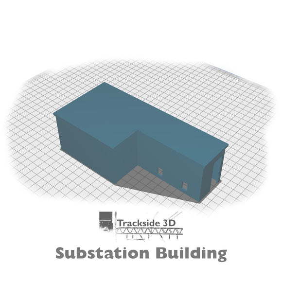
This kit consists of:
- Substation Building
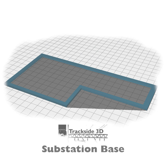
- Substation Base
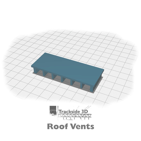
- Building Roof Vent Structure
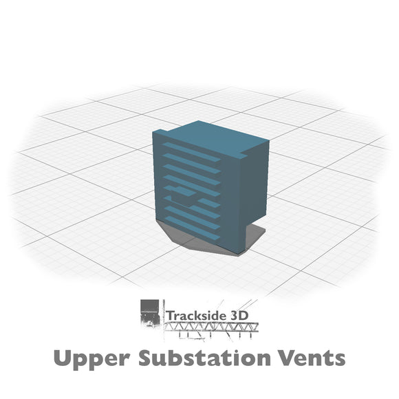
- Upper Substation Vents
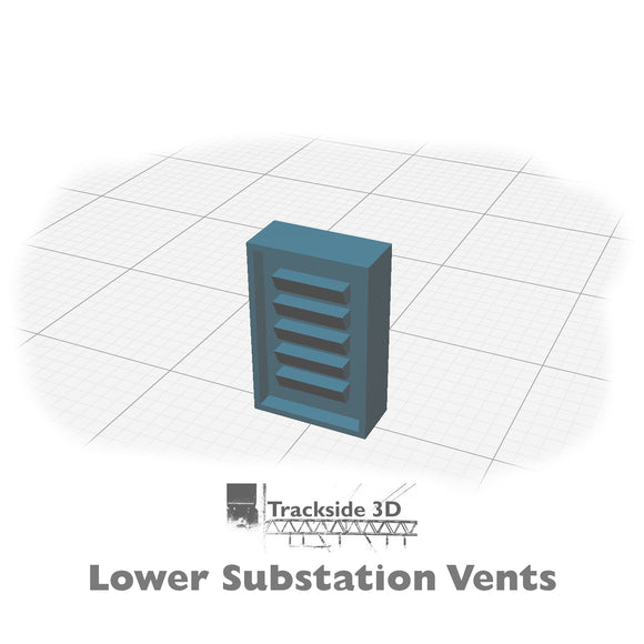
- Lower Substation Vents
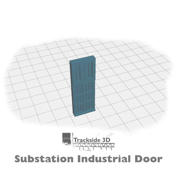
- Industrial Door
You will need to print the lower substation vents (x2), and the upper substation vents (x12).
Model constructed from data obtained from:
- Structures researched from Southern Region BR documents and diagrams
- Kent Coast Electrification - Part 1 (dated May 1959)
- Satellite, photos and video data obtained of surviving structures
- Historical documents and images owned by oorail
- 3D mapping imagery and video analysis from the region
- Analysis of film and images to verify dimensions obtained from satellite data
Construction:
- Check that the substation building fits into the base
- If not, check your settings or strip / sand the base - it is an exact fit
- Prep and paint all the parts
- The main building can be either painted, decorated with brick texture paper or brick textured/embossed plasticard. We recommend the use of Scalescenes.com brick texture paper. It can be easily applied with 3M spray adhesive.
- Place the base on your layout in the desired location
- Check to make sure the decorated building still fits in the base
- Check your rolling stock clearances with the building in place (if applicable)
- Use PVA to glue the Building Roof Vent structure to the top of the building
- The roof vent structure should be glued to the roof of the narrow section of the building. The edge of the roof vent structure should be 10-12mm from the edge nearest the door and glued centrally between the other two edges.
- Once the root vent structure has glued and dried. Insert the upper substation vents into the holes in the roof vent structure (x12)
- Insert the two lower substation vents into the two vent holes in the wall
- Install the completed building into the base on your layout
- Insert the door in place (tip: you may want to insert the door before inserting the building into the base)
- Look for other Trackside3D Third Rail products to complete the look and feel of your third-rail sub-station area.
Product title
Vendor
$19.99 USD | $24.99 USD
Product title
Vendor
$19.99 USD | $24.99 USD
Product title
Vendor
$19.99 USD | $24.99 USD
Product title
Vendor